")

We are frequently asked what a signal-generator like WaverAD is and what it is used for. Admittedly, this question comes typically from people who are not deeply into electronics, but also from our customers we regularly receive questions like:
- What is the difference between a function-generator and a signal-generator?
- What makes an arbitrary signal-generator or waveform-generator?
- What is a logic pattern generator?
- How does such an arbitrary signal-generator work?
It is the intention of this article to shine some light to these questions.
What is a signal-generator needed for?
Function-generator, logic-generator, signal-generator, arbitrary waveform- generator - ???
How does a signal-generator work?
What is a signal-generator needed for?
As the name tells, the basic functionality of an electronic signal-generator is to generate one or multiple electric signals.
In this meaning, electric signals are temporally changing voltage values, following a certain specification. Such specification can be for example a continuous analog-electric waveform like a sine wave (pict. 1a), a square wave (pict. 1b), a triangle wave (pict. 1c) or a sawtooth wave (pict. 1d).
Another signal specification could be to just generate a certain area (e.g. a single period) of such a waveform as an electric voltage (pict. 1e).
|
|
| Picture 1: Different analog waveforms |

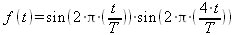
Equally, a signal specification can be to generate an electric waveform from any other mathematical function. An example of such is shown in picture 1f. The function of this voltage waveform is for example:
Signals do not necessarily have to be analog. Digital patterns can also be specified to be a signal to be generated like for example the synchronous parallel data stream as shown in picture 2.
|
|
| Picture 2: A digital signal |

But where are such signals and respectively a signal-generator needed for?
The answer to this question is short:
A signal-generator typically generates the user-defined input signal to an electric circuit that is about to be tested. The respective output signal from the circuit is then received by an appropriate measurement device in order to enable the user to evaluate the functionality of the tested circuit by comparing the received output signal with the output signal that theoretically should appear as an answer to the defined input signal from the signal generator.
|
|
| Picture 3: Scheme of a test chain with signal-generator |

A very simple case of such a measurement environment could be for example the test of a light bulb. To verify that the bulb is good, it is first screwed into the socket, effectively building the electrical circuit under test. In such case, the signal-generator would be the light switch that delivers the electric input signal “Power on” and “Power off”. The measurement device for the output signal would then be the eye of the user that expects to receive for a theoretically well-functioning circuit under test the output signal “light on” and “light off”.
It would become a bit more complex if the circuit under test would be for example a HiFi amplifier. In this case a CD-Player could be an imaginable signal-generator, while the measurement device could be the users ears. Such measurement environment could then at least be used to test the very basic functionality of the amplifier. But are the ears and the input signal from the CD-player sufficient to reliably test the filter functions of the built in equalizer or even values like harmonic distortion?
Such field of application could already be a very good case, where other input signals and measurement devices could be reasonably used. Such a measurement device could be for example an oscilloscope and the input signal could be generated by a dedicated signal-generator.
Many of today's electronic circuits in deed can only be tested using such advanced signal-generators and measurement devices.
Function-generator, logic-generator, signal-generator, arbitrary waveform- generator - ???
Whoever has got involved with the topic of signal generation, might have been struck by some terms that eventually were confusing. Especially the devices used for signal-generation offer a wide variety of characteristics. We want to use the following abstract to clarify some of those concepts.
Function-Generator: Typically a function-generator produces periodic electric signals. In most cases a function-generator is limited to a number of commonly used waveforms (sine, rectangle, triangle, sawtooth, picture 1a to 1d). Such signals can then be modified in their amplitude, offset and frequency (pict. 4). While elder function-generators generate their waveforms by using analog electronic circuits, more modern function-generators use digital signal generation techniques in combination with a consequent digital to analog conversion. Function-generators are typically not designed to generate non-periodical signals (e.g. pict. 1e), complex mathematical functions (pict. 1f) or digital signals (pict. 2).
Wikipedia about Function Generators
Logic-Generator: : Often also referred to as „Logic Pattern Generator“ or „Digital Pattern Generator“. A logic-generator is a signal-generator that is specialized to produce digital signals (pict. 2) and can typically arbitrarily programmed. Depending on the use case, logic-generators offer a variety of signal widths (e.g. 8-Bit, 16-Bit, 32-Bit) and can be adjusted to commonly used logic voltage levels (e.g. 3,3V or 5,0V). Functions like continuous amplitude- and offset-adjustment however are usually secondary in logic-generators.
Wikipedia about Digital Pattern Generators
Signal-Generator: Signal-generator is the umbrella term for all devices that are used to generate specific signals. A function-generator for example is a signal-generator, just as a logic-generator is one.
Wikipedia about Signal Generators
Arbitrary Waveform-Generator (AWG): Also referred to as „Arbitrary Signal-Generator“. The term “arbitrary” means that the waveform that is intended to be generated hasn't been predefined within the signal-generator, but instead can be individually programmed by the user. With that, an arbitrary waveform generator can be flexibly adjusted to the most different input-signal specifications. Next to the typical functions like frequency-, amplitude- and offset-adjust, some of such devices offer a wide range of output options, allowing the generation of almost all imaginable waveforms (pict. 1a-1f and eventually even pict. 2).
Wikipedia about Arbitrary Waveform Generators
|
|
| Picture 4a) Sine wave reference Picture 4b) Changed amplitude Picture 4c) Changed offset Picture 4d) Changed frequency |

How does a signal-generator work?
In terms of its working principle, the simplest form of a signal-generator is the analog function-generator. Using a Schmitt-Trigger in combination with an integrating circuit, both a triangle waveform and a rectangle waveform can be generated. A connected sine shaper circuit then approximates a sine wave as an additional waveform. Different methods within the signal generation chain can be used to set the frequency of these signals.
|
|
| Picture 5: Analog signal generation chain |

Different microelectronic devices exist in the market that integrate the above signal generation chain into a single IC.
The different waveforms produced by the signal generation chain can then be switched individually into a signal amplifier which drives the output of the function-generator. Such amplifier can be used to adjust the amplitude of the output signal as well as to add an offset to it.
Disadvantages of such a function-generator are the limitation of the producible output signals to just a few different waveforms as well as the ability to generate such signals only as periodic waveforms. Furthermore the quality of the signals is often limited due to the use of the analog signal generation.
To increase signal quality, more modern function-generators often use digital methods to generate the waveforms.
One of these methods is the “direct digital synthesis” (DDS). Function-generators using this technique store the desired waveform as a reference in an internal memory and sample this waveform depending on the requested output frequency.
Wikipedia about Direct Digital Synthesis
Picture 6a and 6b1/6b2 show the working principle of DDS.
|
|
| Picture 6: Digital signal generation options 6a): Reference-Waveform in signal memory 6b1): DDS - Use of every 2. memory values with sample rate fs 6b2): DDS - Use of every 3. memory values with sample rate fs 6c1): Use of every memory value with low sample rate 6c2): Use of every memory value with high sample rate |

However a huge disadvantage of DDS is that depending on the desired output-signal frequency, not all of the signal values in the signal memory get sampled to the signal output. This can lead to undesired artifacts in analog signals, however for digital signals, a non-sampled signal value can mean a significant and unacceptable destruction of the signal. Hence, signal-generators that have the ability to produce both analog and digital signals cannot make use of DDS.
In such case and alternatively to DDS, the signal stored in the memory can be sampled by an PLL-adjustable sample frequency to produce the desired frequency of the output signal. Using this method, really all signal values in the memory get sampled and used in the output signal.
Picture 6a and 6c1/6c1 show the working principle of this digital signal generation methodology.
The waveform sampled from the signal memory is then converted into an analog signal using a digital to analog converter and thereafter conditioned by an output amplifier. Amplitude and offset-adjust can happen both in the digital memory as well as in the output amplifier.
A very generic problem of the digital signal generation is the need to filter the analog signal after it has been converted in the digital to analog converter. On the one hand it is desired to “even out” the quantization steps in the signal, on the other hand “edges” and “peaks” of for example rectangle- or sawtooth-signals shall not be “slurred” - and this shall be valid through all adjustable frequencies of the output signal.
A compromise is unavoidable for the filtering.
Picture 7 shows the schematical structure, as it is used in the arbitrary signal-generator WaverAD.
|
|
| Picture 7: Schematic structure of the WaverAD signal-generator |
